During an underground utility survey, we were searching for a pipe which was supposed to be made of reinforced concrete. The pipe was about 4 feet in diameter and the depth to its top was about 7 to 8 feet. It's a big pipe, but unfortunately it's too deep to see it using our ground penetrating radar (GPR). After considering all the options, we decided to try electromagnetic (EM) mapping due to target and site characteristics. The survey area was a landfill area.

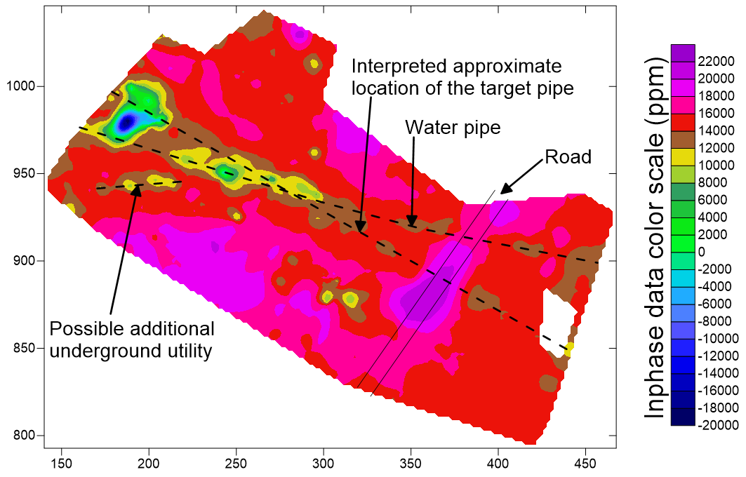
As the picture shown above, despite extreme variations of local geology, the target pipe still showed up in the EM mapping, although partially/intermittently. Its closeness to a shallower metallic water pipe made the data interpretation more difficult. The water pipe had been located with a cable/pipe locator before the EM mapping survey. An additional possible underground utility was also identified through the EM mapping survey; it could not be detected by either our cable/pipe locator or our GPR, possibly due to its characteristics (materials, depth, etc.). This example is not a typical showcase for EM mapping where everything shows up beautifully; rather it shows difficult realities we often face in underground utility locating.
Besides two kinds of "standard" tools - pipe/cable locators and GPRs, there are other tools/techniques for underground utility locating, including EM mapping, magnetometers, metal detectors, etc. As geophysicists, we know it, but we are constrained by clients' budgets. Applying all techniques for every site is simply not practical, not to mention exhausting varieties of parameters/settings for each technique. But knowing their existences, and more importantly, understanding their advantages and constrains, come in handy from time to time for underground utility locating.


